
WarBlock Receiver Height AR15 Gas Block CNC Machining (11): 3D machining lightening pocket and sling swivel socket
As hoped I was able to get some machining done this week. In this episode I wanted to begin operations on the lightening pocket which always seemed somewhat daunting to me. When I first bought my CAM software a few years ago the first thing I did was try to figure out how to do this feature using 3D milling and it left me feeling a bit intimidated. However it is one of the few remaining major operations so I figure just jump in and see what floats. Well I don’t know what is floating but I certainly know what sinks, may bank account, in the form of carbide endmills. The first attempt at this pocket left me with more carbide to add to the broken pile.
My thinking was that since a square endmill is prone to chipping and a radius corner endmill less so, then a ball endmill must be even more so. This combined with the prospect of how long 3D milling can take led me to turn up the feed on these cuts. The first op I did was simply to pocket out the main flat bottom area. I tried a ramp angle of 10 deg. which chattered but the actual cut sounded OK for the most part except for the chirps resulting from the ballmill engaging too much material in a 90 deg. or tighter turn. Right at the end of that op the turns start to become more and more acute and the radial engagement starts to become more abrupt causing tool flex. You can actually start to see the ballmill flex a little on the few passes before it just snaps. The flutes never chipped though. On the bright side it did not take too long and the finish was incredible with a 2% stepover. Even though the floor of that pocket was simply done with successive passes of a ballmill it appeared to have been face milled with a flat bottom cutter.
After some deliberation with my CAM I decided to first relieve the area where those tight turns were to be made using a back and forth ramp. In another post I mentioned needing to modify the model to be better suited to using a 0.1875″ ballmill. What I did was change all the radii of that pocket from 0.1″ to 0.09375″. This means I could cut the majority of the curves of that pocket with a single pass of a 0.1875″ ballmill instead of many passes.
After breaking my only 0.1875 ballmill on the initial profile op I ordered a few more from Lakeshore Carbide but this time instead of getting a standard length I got the stub length for added rigidity, I don’t use much DOC anyway with these. The stub length ballmill has a reduced flute length so that the shank portion (the strongest part) comprises more of the tool.
Lakeshore Carbide stub length ballmill
You can see the difference in flute length between the stubby and broken standard length ballmills here
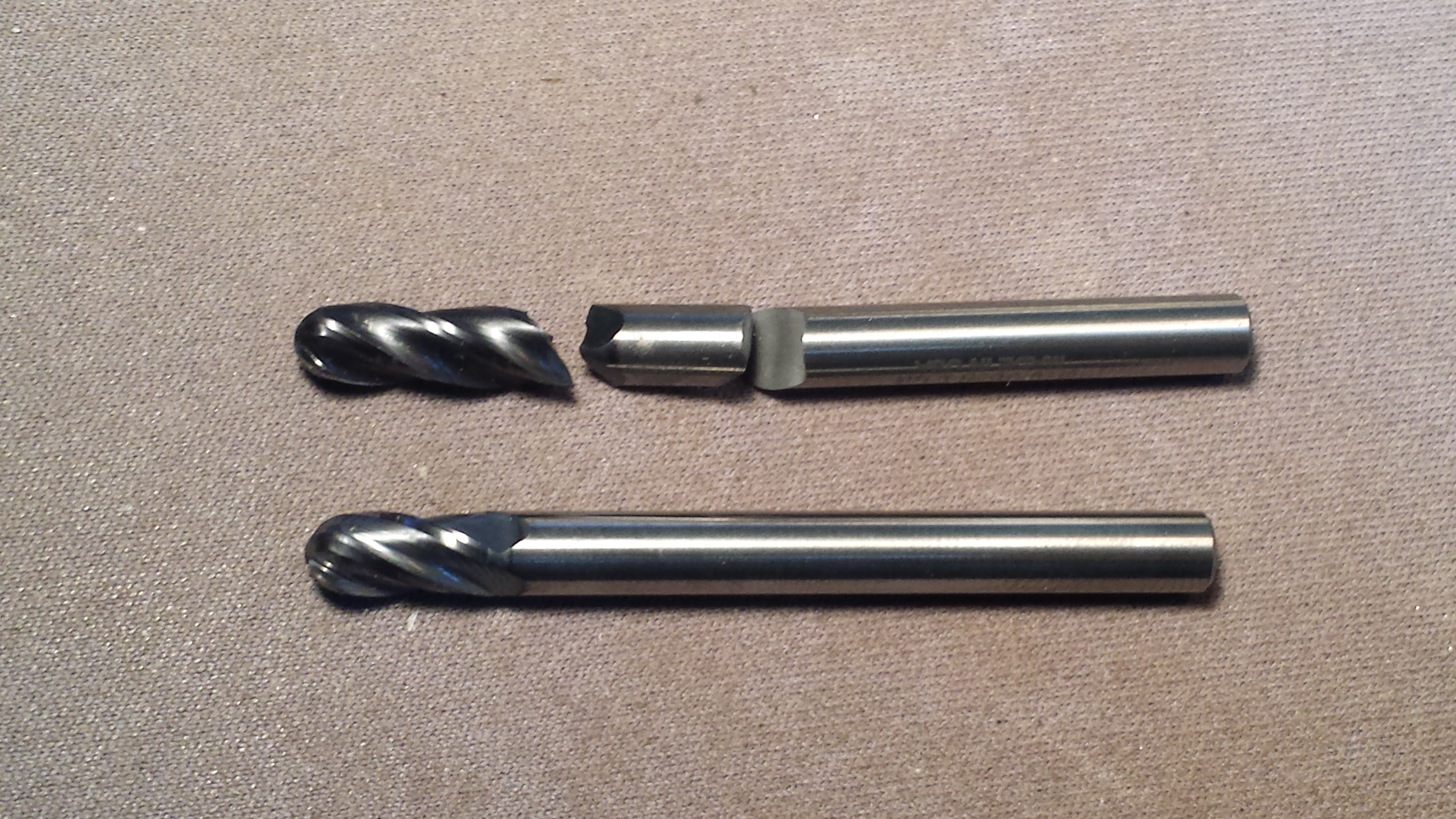
broken Maritool vs Lakeshore Carbide stub length ballmill
So going back and making a clearance slot involved a back and forth 3 deg. ramp which did not turn out overly well due to chatter. I’m not immediately sure how to deal with this other than to slow the rpm down or decrease the ramp angle even more. Nevertheless it made the cut and cleared out the material albeit leaving a chattery finish on the vertical wall.
Since the first pocketing op resulted in some sharp corners I went back and massaged it a little with arc fitting and cut rounding, both features of RhinoCAM. This simply fits arcs anywhere they can be fit depending on what tolerance threshold you set and also rounds any change in direction so that these transitions happen much smoother with less shocks to the tool.
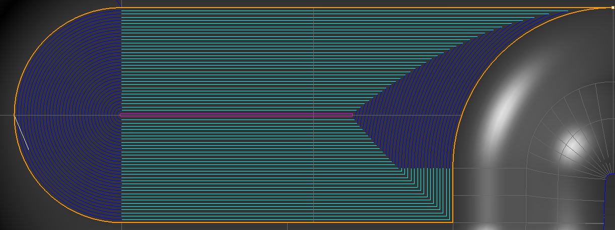
2% stepover with no cut rounding

4% stepover with 0.015″ cut rounding
Ultimately the latter cut with the rounding will be smoother but I think I will change back to the 2% stepover and see what that looks like. When dry running the code many of the blue arcs resulted in full circles instead of half circles in Mach so I found out that you must check the “limit arcs to 180 deg.” box in the post processor so they will path correctly.
Running the simple profile pass around the edges of the pocket resulted in a beautiful finish without the need for numerous passes.
Now onto the 3D machining. I played with numerous 3D techniques but ultimately parallel finishing made the most sense so as not to require any hand manipulation of the code. I lifted the path off of the model by 0.002″ to be on the safe side for getting a nice natural organic blend of the contours but it still cut too deep. I attribute this to the actual part being slightly over sized from deflection. I have two options here. The simplest is to just raise the toolpath a little more off of the model to maybe 0.004-0.005″ and see what that looks like. I’m betting it will be fine but if not this 3D toolpath has a feature called radial loops. This causes the tool to gently retract radially away from the model, do a loop in the air to more over the step, then gently radially re-enter the cut. In fact this is such a cool feature that I might use it anyway and of course document the details when I revisit this operation in the near future.
Next I completely rethought the bottom ops and programmed the sling socket swivel feature. I decided that I wanted to do even less machining on this side than I originally thought. Just enough to get the sling swivel socket profiled, rounded over, and then the drilling and bore done. This feature had me a little perplexed about the best way to approach it. I wanted to minimize tool changes so if I could reuse one of the tools I was already using I would. Normally the bore would be drilled then finish machined but the fact that I needed to drill the gasport hole off center made me think the drill would wander badly. I contemplated plunge milling with the 0.375 rougher since I was already using it and it was the right size but was dissuaded of that notion. The next option was helical interpolation using the remaining available tool, the good ole 0.1875″ endmill. Carl at Lakeshore Carbide suggested this would be the better option as well. Fearful of chipping flutes tips as I always am I figured “hey they are already a little chipped and this endmill is a heck of a lot cheaper to replace than the 0.375″ rougher” so I ventured forth.
Again I was amazed at the sound (or lack thereof) of the 0.375″ rougher just quietly pushing it’s way though those heavy cuts, and this endmill is starting to show some wear on it. The slotting with the 0.1875″ endmill is still a little irritating to me because even cutting the DOC in half didn’t seem to change anything about the chatter. Next time I may reduce the RPM to see if that helps. The roundover is still ever so slightly too tight so I will widen the berth a tad more to avoid making a ledge.
The interesting part in that I’ve never done it successfully yet is the helical interpolation. I keep hearing about how it is so much better than anything else out there from places like Sandvik Coromont I thought this better be good. The last time I tried it years ago I ruined a $98 endmill within 30 sec. The very idea doesn’t sit well with me what with the flutes tip engaged from both the side and the bottom. It’s like they are just begging to chip. However people like Brad from Tactical Keychains does it all the time like in this video of machining the notorious grade 5 titanium and he’s getting good tool life. So I gave it a shot.
I went with the often recommended 3 deg. helix angle instead of the 7 to 9 deg. angle recommended by GWizard’s interpolation mini-calc. but I used its recommended RPM and feedrate. It made the hole without breaking the endmill however the flute tips were predictable (by me) chipped. They were already a tiny bit chipped from the Mach3 brain shart in the previous video but they were much worse now so I can’t necessarily lay blame to the cut itself, which sounded good. I know when a tool get chipped it begins on a rapid course to failure so this could be the case here and not the helical cut. I had tons of coolant forcefully shooting right in the hole and there was even the drilled through hole for chips to flow out of. I didn’t even really hear much chip re-cutting if any. Nevertheless I have opted to replace this endmill with again one from Lakeshore Carbide that has a 0.010″ corner radius thinking it might resist chipping better as well as perhaps making better cuts.
Lakeshore carbide corner radius endmill
I chose the 0.010″ radius but may be inclined to try a larger radius in the future depending on tool life.
Now the crazy part was after the helical interpolation was done a coding error caused by some idiot who shall remain unnamed resulted in the finish pass to run at only 1300 RPM, much slower than any recommendation from GWizard that I could get. To my shock the cut was silent and the finish looked like a precision ground and lapped bore, it was that perfect. It’s so reflective I can’t even get a decently convincing picture of it, and it all happened by accident. The bore size was also spot on as the sling swivel stud fit it perfectly without rattling. This diameter dimension going from 0.375″ to 0.377″ was another change to the model I made recently and it definitely paid off, 0.375″ would have been too tight.
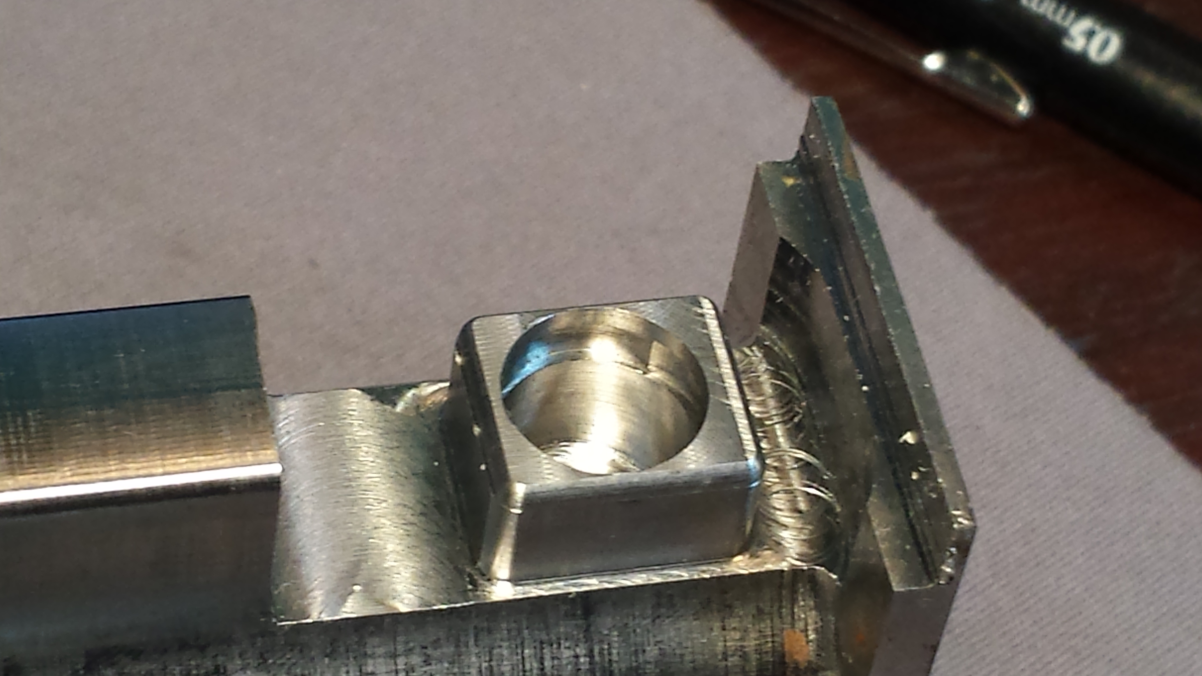
amazing finish: 1300rpm 4ipm 0.4 DOC 0.001 WOC
Onto the sling swivel stud capture groove. I was able to use the Woodruff cutter for the first time and it cut just fine. If you look closely in the bore you will see the unique clover leaf like geometry of the groove. This is called a rotation limiter and it prevents the sling stud from being able to fully rotate around and get the sling twisted. The only issue with this op is that the sidewalls bulge just a little where the groove is cut because the stock material is too thin here. I can either change the model to tighten in the groove since I made it slightly too big by about 0.0025″ per side or widen the whole feature. Or perhaps both since I don’t want to widen it too much because it’s designed to be thin enough to fit inside of a forearm rail but yet don’t want to tighten the groove too much risking not working with slightly over sized stud bearings. Maybe just a little with each.
I just realized that all of the features of this gasblock have been cut one way or another (except the back which is just milled off). Now it is just a matter of refining the cuts to eliminate chatter, preserve tool life, and make accurate dimensions as efficiently as possible with the best possible surface finish.
Thanks for reading and see you in the next installment.