WarBlock Receiver Height AR15 Gas Block CNC Machining (7): side gutting and 3D profiling
Things are really starting to take shape and the new fixture plate is working out great. The setup seemed very rigid to withstand some relatively heavy cuts and also very accurate and repeatable. We are finally to point of making the horizontal cuts which involve primarily gutting the side profile out and 3D contouring. The main challenges in my mind were the rigidity of the setup with regards to heavy roughing and secondly the the feasibility of 3D machining in rearward most portion of the gasblock where the little 0.125″ ballmill would be repeatedly plunging and gouging through a decent amount of steel. Both fears were laid to rest after I held my breath and just decided to step away from the CAM program and simply try the cuts at the expense of potentially losing some endmills. The cuts turned out great and they give me an excellent starting point to make minor tweaks here and there.
First was the slotting with 0.375″ roughing endmill. I decided to refrain from trying to do it it all in one pass for two reasons: First the deflection may be too high causing chatter (but I would be willing to try it), and second and more importantly is that the remaining island of material would not fall far enough away from the part on the two inside pieces due to them being right over the vice and would certainly cause a tool crash. I need all of this material to end up and small chips to be washed away by the flood coolant.
The bayonet lug machining was pretty straight forward so no need to rehash that.
On to the new machining strategy that we have not yet implemented; the 3D profiling. In this case I chose the “horizontal finishing” toolpath strategy which is most appropriate for parts with steep sidewalls such as we have here. Horizontal finishing follows the contours of the part while taking steps down in the Z axis at at set increment. The program does most of the work here but it is still a little tricky to get the toolpaths coherent enough to make sense. I had to draw containment regions for different areas so as to avoid a deluge of rapids and retracts.
As you can see in the two images below, the one on the left is with using containment regions to split up the machined areas into 4 different regions each treated separately. The one on the right is just using a containment regions that surrounds each leg of the gasblock dividing it into only 2 machine regions. Notice all of the retracts and rapids denoted by the red in the right image compared to the fewer number in the left image.
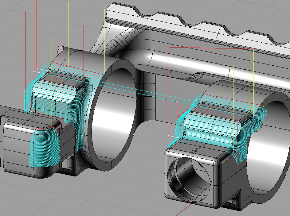
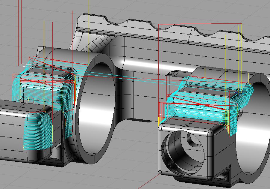
Also note the tighter stepover of the rear toolpath versus the front toolpath. It may be hard to see but the rear one of 5% is more “blue” with pathing than the 7% stepover of the front.
There are other 3D operations that need to happen while in this horizontal orientation but I decided to alter the model slightly to accommodate a different and faster machining method which necessitates the use of a different tool that I don’t currently have. Barring the immediate lack of tooling, the lack of time has always been my nemesis and is now trying to claim me. Unfortunately, recent family circumstances will now leave me even less time to work and will relegate me to the wee hours. I still plan on striving to be at least as productive as I have been in the past but my content may come spottily for a while. Please continue to follow the blog and I will continue to produce as much timely content as I can.