
WarBlock Receiver Height AR15 Gas Block CNC Machining (3): machining ops on front side of fixture 1
After spending some time CAM’ing a profile machining operation to cut out the general profile of the gasblock I took it to the mill a cut it out while on the fixture plate. It was great…but you can’t see it. Why? I don’t know why. I recorded about 30min or so of great footage from different angles, went to edited it and it simply wasn’t on the camera. Perplexed I ventured on with the intention of milling it again and recording it but right off the bat those plans were put on hold. I did however manage to recorded some new footage today and actually got to break a 0.5″ roughing endmill. Just shattered it. Sadly since that was my last 0.5″ roughing endmill of that length there would be no profile machining today. I don’t know whether to feel miffed that I just exploded an $80 cutting tool or proud that it broke before the spindle motor stalled. Either way it ended up being a catalyzing event that prompted me to call Carl at Lakeshorecarbide , introduce myself, and talk shop for some time. He was exceptionally eager to help and really took an interest in my issue. Needless to say I will be getting much more of my tooling from him from here on out.
In this episode are the first machining ops on the fixture plate and here we are trying to machine everything that can be milled from the front side, which consequently is where most of the material removal comes from. As I mentioned you can’t see the cutting video but I do have the CAM simulation.
I first began by mimicking a high speed machining tool path or one that has constant radial tool engagement to remove the bulk of material
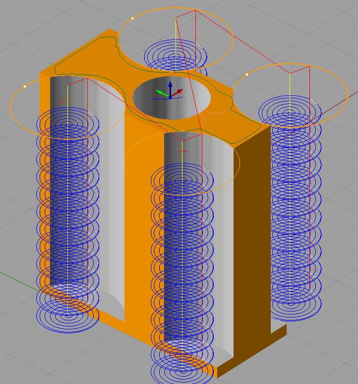 Basically this is a technique that limits the amount of radial tool engagement to avoid sudden surges in cutting forces which result in tool deflection and chatter. The closest thing I have at my disposal to this is the simple spiral. With a spiral tool path you can program in a certain width of cut and be certain that the engagement percentage will not spike suddenly or even increase. This can have a dramatic positive impact on tool life as well and the bank account.
I have tried cutting the profile out as is (the green outline in the above image) but it always resulted in quite a bit of chatter in those 4 areas where the spirals are. These areas are also the deepest radial parts of the cut and at the deepest is approaching 0.35″. Chatter in that case could only be dealt with by slowing the feedrate down to a crawl and even then it really only lessened it. By removing this material first by taking relatively light widths of cut and a relatively deep depth of cut but at a fairly quick feedrate we clear the way to run the actually profile at a more reasonable feedrate without the significant increase in chatter when the tool enters those areas.
I didn’t mention it in the video but each one of those spiral columns is removing material from 2 stock blocks at a time. Imagine there are other blocks on either side of the one in the image that are also being machined as well leaving about a 1/2 inch gap in between for the tool to plunge to depth unfettered and for chip clearance during the cut.
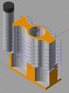
Here is the remaining roughing toolpath
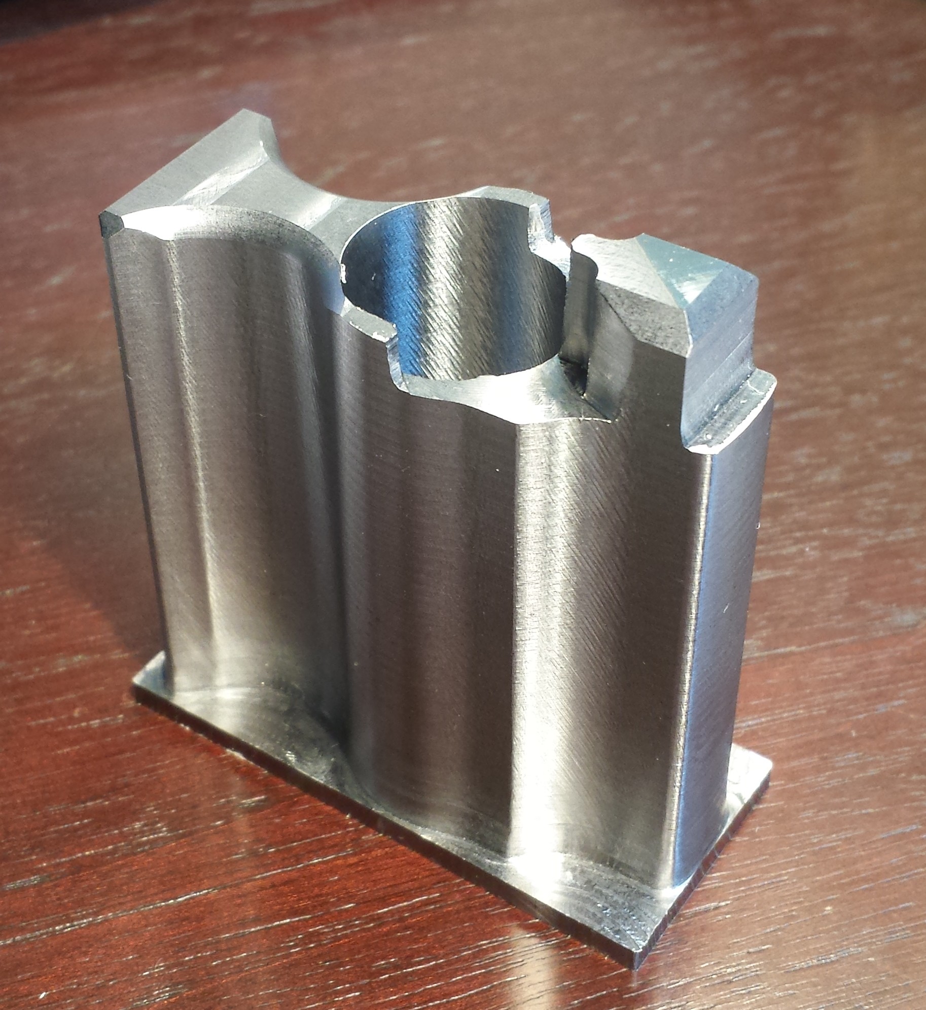
The other cuts in the video may need some tweaking here and there, especially the ones involving the 0.5″ endmills but the rest turned out stellar. I had tweaked the radius and the chamfer cuts a couple of years ago since that is about all the old spindle motor to reliably handle without stalling so they are pretty spot on.
Here is a concomitant image of the machined part
The next installment will either be another similar operation with some tweaks and some new Lakeshorecarbide tooling or I may hold off on that and go ahead and mill the recoil grooves in the Picatinny rail from the top orientation. Whatever I can get to first.
looking forward to this one