
WarBlock Receiver Height AR15 Gas Block CNC Machining (16): soft jaws and milling off back tab
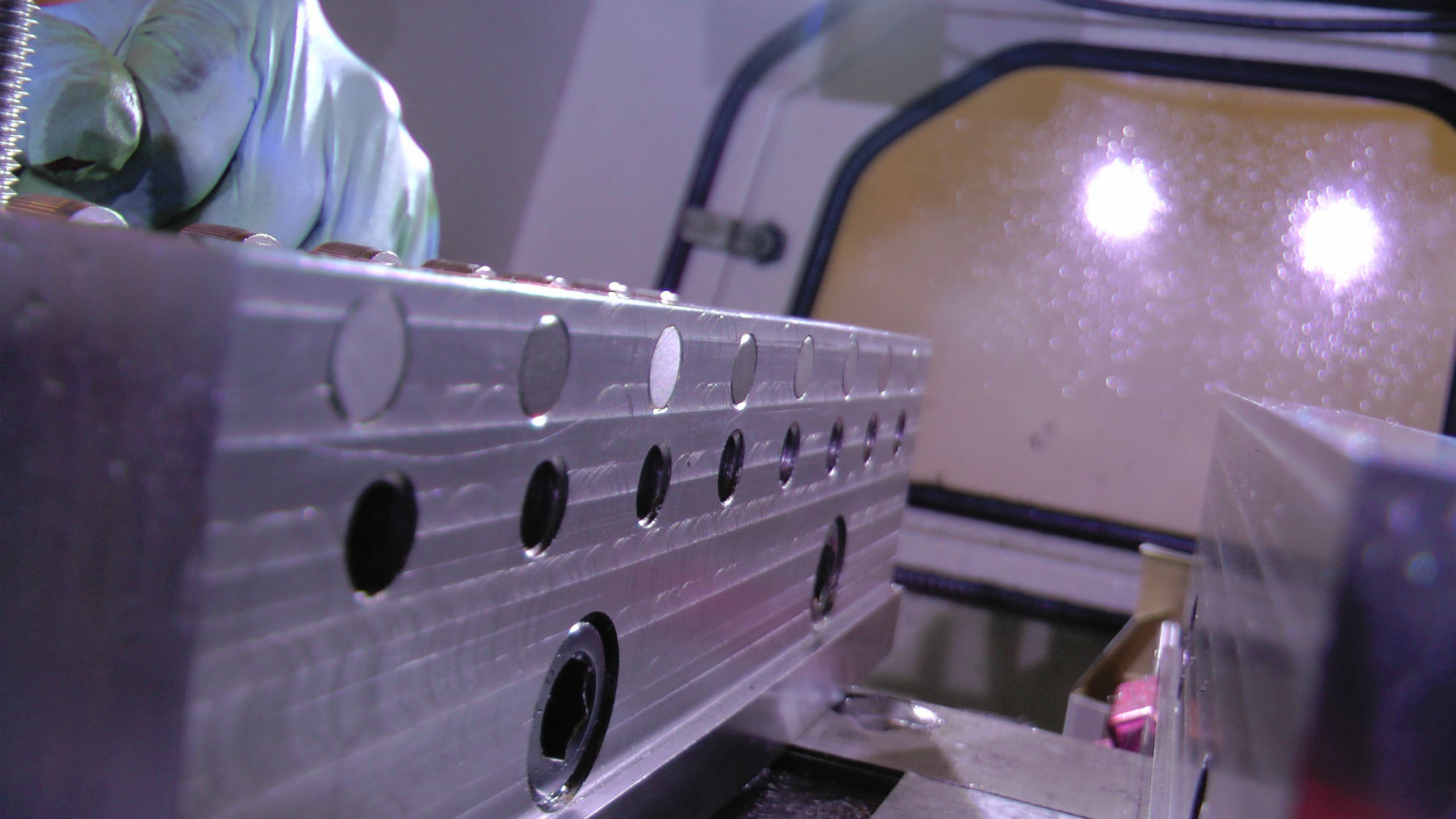
After the excitement of the first production run we need to float back down to earth for a little bit and face the reality that these gasblocks still aren’t done. We need to remove the back tab that has been securing into the fixtures up to this point. While it sounds easy enough it was actually quite a complicated little thing to tackle. First off I had to design a set of “soft” jaws to hold the things now that they are a nice irregular shape with very few flats and a tendency to crush or deform if clamped too tightly. I say soft jaws in quotes because they are not actually very soft, rather than the soft aluminum they are traditionally made from I decided to make them out of hardened 4140 steel just like the gasblocks. In fact I actually made them from the very same bars I buy to make the gasblocks with, so out of two bars I get two vise jaws and two gasblocks. Here at War Machine we are always looking for economical ways to do things so we can pass the savings on to you.
With that said, let us begin with part one of the multi-purpose soft jaw series within a series.
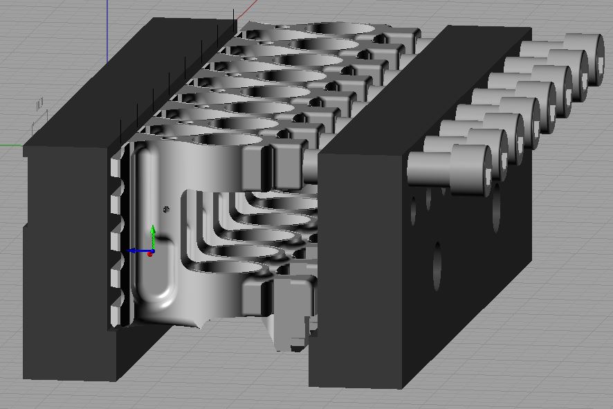
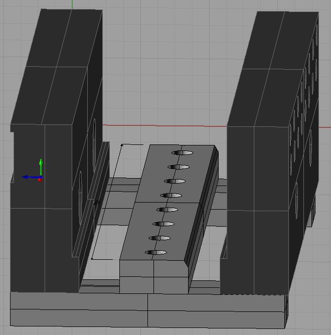
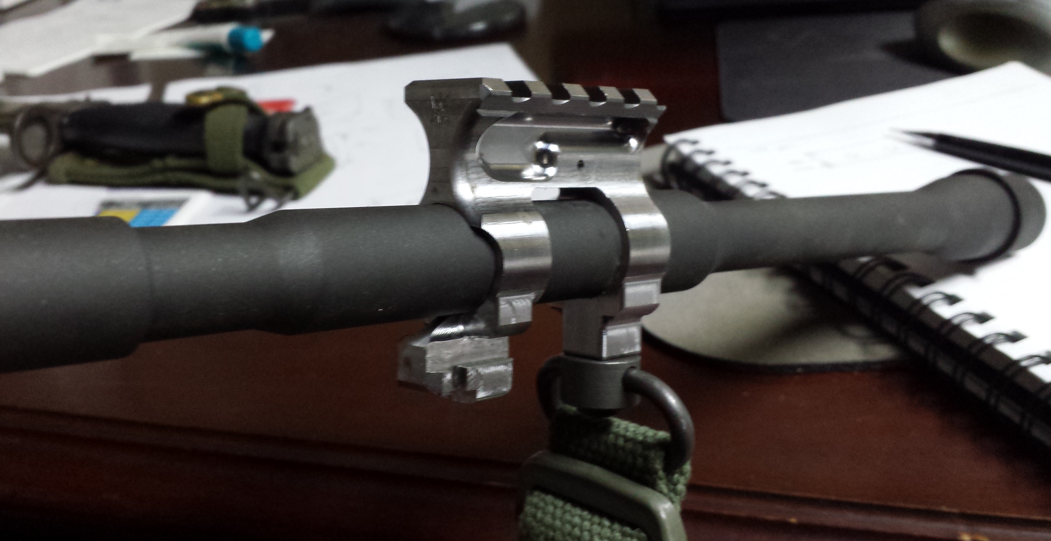
First off these jaws had better be able to serve numerous roles to justify the time, expense, and design work tied up in making them so for part one we are just going to focus on the primary objective that these jaws accomplish and that is milling off the back tab of the gasblocks. As with all of our other fixtures we are going to try and harness some economies of scale and the power of CNC by creating jaws that can hold as many gasblocks as there are coming down the pike to eliminate any potential bottlenecks to production. Both fixtures 1 and 2 contain eight stations so we have a target number for the jaws. The only way to hold eight gasblocks in a vice is vertically with the fantail pointed skyward. From this orientation there is no flat for the movable jaw to seat against, in fact the only flat practically available is the one inside the sling swivel socket…I knew I put that there for a reason. So a boss on the movable vise jaw could fit the bill but lets think about that for a moment. The added complexity and CAMing time notwithstanding consider that with fixed bosses any tiny deviation in the gasblocks dimension could compromise the clamping force when the vise in now clamping the largest gasblock and not clamping any others. It’s true the boss would prevent the gasblock from being ripped up towards the endmill but it would not be rigidly held by any stretch when confronted with the whirling helical flutes of a cutting tool. We must devise a way to clamp each part individually. Well, the socket hole is 0.377 in diameter so coincidentally a 0.375 socket head cap screw fits right in there no problem. We have our clamping mechanism. Drill and tap holes to run bolts through the movable jaw but make sure they are spaced such that any out of square tabs are tolerated. I left a tolerance of 0.05″ between the actual tab dimensions of 1.0″ for a spacing of 1.05″. The bolt also need a little bit of work so I squared the faces of them flat with an endmill.
Since I don’t have 8″ parallels and the ones I do have are for the standard height vise jaws I designed in fixed parallels which would support any workpiece where the jaws overhand the vise bed and can be used in conjunction with normal parallels to raise the work to a similar degree in relation to the taller jaws. Of course the main design feature is their height, leaving just enough clearance above the jaws for the back tab to be milled away and they stickout from the face of the jaws only enough to register squareness across the broadest part of the forecastle but yet just shy of the logo so as not to encounter burrs.
For milling I initially wanted to use the big EM90-750A 0.75″ indexable endmill from Glacern Machine Tool using Mitsubishi APMT1135-VP15TF inserts.
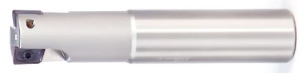
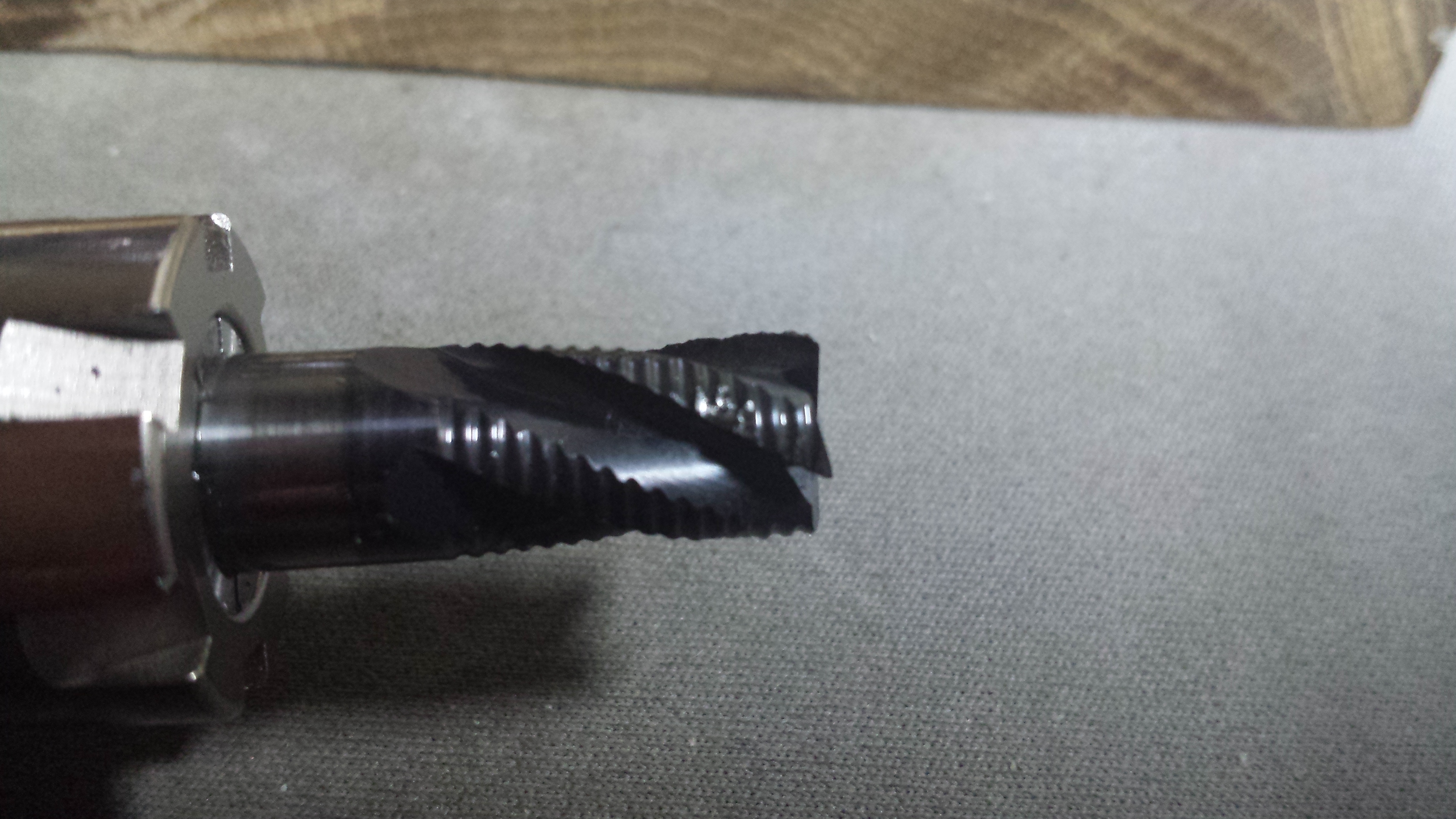
Initial testing suggested this was not feasible. At the depth of cut required (~0.25″) that endmill exerts so much force on the workpiece that is just smacks it out of the way even when clamped traditionally in a vise. Knowing that the gasblocks would be clamped even less rigidly than that I knew it would mean big trouble. I then decided the size endmill that I’ve had great luck with even when the part is not in the most secure setup possible, that’s right, the good ole’ 0.375 rougher. This size is good for not transferring too much force to the work. I’m still using the “Fireplug” from Lakeshore Carbide but it has taken quite a beating with numerous chipped teeth on the cutting edge. Up to this point it is still working so I’m still using it.
Even with this smaller endmill the initial cut testing did not go well. First the part pushed over in the vise and became canted so the cut wasn’t square. Then there were overhangs of steel that broke free from the tab and became loose canons that could damage the fragile carbide of the endmill much like a loose canon that breaks free of its lashings and roles around the ship damaging the hull.
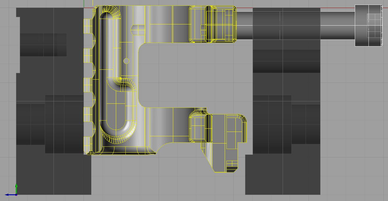
First the toolpath. I chose that Y axis toolpath for a few reasons. One reason was to confine the cut to one part at a time so that if it were to break during the cut at least I could have some finished ones instead of all of them being in a unfinished state, that was probably the least compelling reason. The secondary reason was that I incorrectly assumed that the force exerted on the part was in the axis of motion so I thought by going up and down in the Y axis meant that the part was always being pushed into a vise jaw. However the biggest reason was that there would be fewer interrupted cuts endured by the endmill. When the cutter goes in and out of material it is stressed more so than when remaining in a cut. Despite there being unavoidable holes that the fireplug has to plow through at least it wasn’t also engaging and re-engaging with every part as it went through all eight gasblocks as it would if it were moving horizontally in the X axis.
Well here is why I was wrong. First of all the parts were not rigidly secure right off the bat but here is why my toolpath appears to have exacerbated the problem. The force imposed on the work piece is actually quite lateral to the direction of travel. It’s as if you are mowing your grass and expecting the clippings to be thrown forward in front of you because that is the direction that you are walking. Not so, the clippings and in this case the chips but more importantly the force exerted on the work is in the direction more or less tangential to the rotation of the cutter. So by going up and down in the Y axis I’m actually pushing the part over in the X axis where it is least supported against opposing forces.
Now the problem with the overhangs. That is more of a unique problem per part and in my case this toolpath also made the problem much worse. The overhanging tab, once cleared from connecting material, will simply fall away. However if there is no place for it to completely clear the cutting plane it becomes a hazard to the cutter and possibly to the work as well. My Y axis toolpath ensured that the hanging tab would not fall away.
What I did to remedy this was to change the toolpath to have X axis travel. This pushes the work into the vise jaw and eliminates hanging tabs that can fall into the cutting path. The one hanging tab that does fall away does so right at the end of the cut and I made sure the endmill just barely overhangs the part to ensure the hazardous free tab is thrown clear by the endmill and if it wasn’t at least it wouldn’t fall into the its path. In the words of Brodie from Mallrats, “You face forward or you face the possibility of shock and damage”.

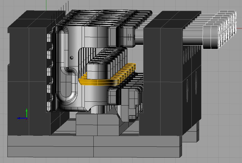
So addressing the simple fact that this setup lacked rigidity I tried to design something quick and dirty that could fix this problem. After a test cut using a bolt for a T-slot I ended up moving forward with a bracket of sorts that has a threaded bar so that the gasblocks can be secured downwards towards the parallel keeping everything square. I used flanged sleeve bearings to serve as washers because they could slip down in the bore of the gasblocks maintaining their alignment without slipping off. I used 3/8-16 x 1″ socket head cap screws since the heads just about fit in the 14mm hole on the gasblock tabs, I had to grind the diameters down a little so they would fall through. I also milled a 60 degree chamfer on the near side of the bar to match up with the chamfer of the bayonet lug. This not only allowed me to center the threaded holes on the bar which make for easier machining since I did most of it manually but it also help to support the bayonet lug and prevent it from flexing when clamping down. The flange bearings also need a little flat and a radius to clear the radius of the forward leg and underside of the gasblock. Nooge.
By just bolting on cross members to the threaded bar this allows them to just slip under the vise jaw overhangs forcing the threaded bar to remain flat and tight to the vise bed. It also can move somewhat freely to reposition for other purposes.
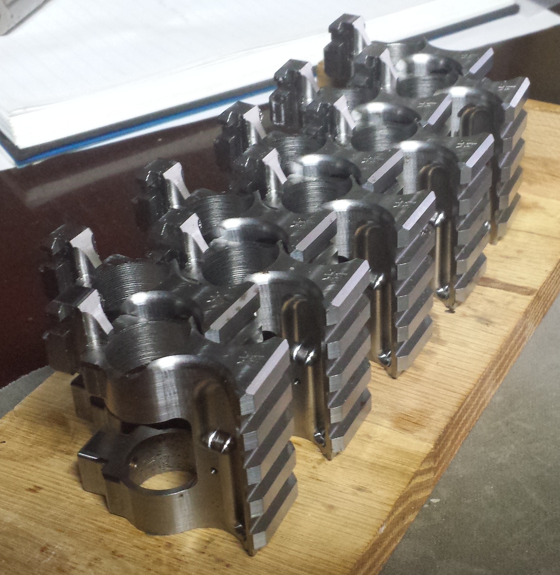
We are finally finished with the machining phase of the gasblock although this is not to say that improvements will not be made, different tools used, or different techniques will be tried to improve the product. These will all certainly happen and of course I will update this blog with them when they do. The next stop is to send these initial space monkeys off for finishing. I was originally going to Manganese Phosphate Parkerize them but have now tentatively opted to have them Salt Bath Nitrided. That is how I wanted to finish them many years ago when shopping around for a machine shop to make them for me but the price was prohibitive. It seems the price has fallen, quality has improved, and is more widely available. don’t you just love the free market. Nitriding is a far superior finish to Parkerizing and very very hard, after all it is the same “coating” that is applied to my carbide endmills to cut hardened steel, and it is more corrosion resistant.
So join me next time for part 2 of the soft jaw mini-series where we will explore the secondary objective of these jaws. Snoochie boochies
I have enjoyed the trials and tribulations of bringing this product to market. I can’t wait to buy one! Nitride finish for the win! Best of luck, James.
Thanks Bruce but there is more to do yet. Isn’t there always. I need to redo some dimensions that were affected by the nitriding. Then I discovered that the crust left over from the nitriding process was only built up around sharp edges so I’ve decided I need to tumble them in some abrasive media in my vibratory tumbler before I send them off. They bead blast them but the that isn’t aggressive enough. I was going to get some ceramic media from McMaster, any suggestions? I think you were experimenting with media recently. Something moderately aggressive to soften all the sharp edges in a relatively short time (1-2hrs).
Then there is the problem of nobody knowing about it (relatively speaking) I need to figure out a marketing campaign. That is going to be harder since I was banned from Arfcom earlier this week. I don’t even know why for sure. My account and posts were just deleted. I tried contacting them to no avail. I had a thread going on there about my gasblock for several months, then Sunday night I just posted some updated pics of the machining process and boom, gone. I’ve been shut out. Too bad it seems there was a lot of interest there.
How would you like to be the very first gasblock customer? 300 Blackout maybe… I’m going to let the blemished ones go for $65. That is more than half of what I expect retail price to be and an insanely good deal.
Fixture design really is an art.
I would have inserted dowel pins into each gas block and made the movable jaw a row of v-blocks to prevent crushing the bore at all. You could toe clamp dowel pins in pairs to the back jaw in case there are dimensional variations that a movable vice jaw wouldn’t compensate for. Either way should load the machine faster and more firmly. Beyond two similar parts I go for double vices or stand alone fixtures.
I would also think about inserting small dowel pins into the fixed jaw to locate one side of each gas block both high and low to prevent roll around the machine Y axis (Yaw around the part Z axis). Probably in the middle of a Picatinny slot.
I always try to locate my parts in three of the six possible directions a part can squirt out of a fixture. Usually in complementary directions all to one corner or edge. Also pitch, roll, and yaw. Just preventing the part from leaving the vice (like the sling socket screw) doesn’t mean it’s indexed.
Don’t be afraid to program mandatory stops to add extra clamps to prevent vibration like when you mill the bayonet lug slots unsupported. Also side mill in one direction to up the cutter life. Look into reduced shank bull end mills to prevent wall taper from that 2.5″ flute.
Hope this gives you some helpful ideas. Those were just the things my brain was screaming at me as I watched. The design is great, nicely sculpted edges, overall excellent programming. Good results from such a small mill. I hate to see people chasing their tails with fixtures, usually people that start with CAM instead of handwheels and a notebook.
Thanks very much for the tips. I thought a lot about some of the ones you suggested like the dowel pin in the bore idea and somehow securing the yaw using the Picatinney rail slots although I thought of just making a long square key that would fit in the rails slots of all of them kind of lock them all in place at one time so they couldn’t tilt. That was my backup plan if the through bolt wasn’t rigid enough. Turns out it is so I didn’t need the added step. The current design is not perfect by any stretch and a lot of it was simply a compromise between how much time I wanted to spend on making them vs what is the simplest way to get it done and be reasonably effective. I’m sure I will come up with better ways to do a lot of things as this product starts to roll out. I hope you stick around and offer more suggestions, you seem to have a very keen eye for these things.