
WarBlock Receiver Height AR15 Gas Block CNC Machining (10): chatter and interpolation
It’s been awhile since my last video or blog post due to too many extenuating circumstances to mention but I’m back with another one. This one will be yet again of particular interest to my machinist friends and perhaps no one else. From the last installment I was playing around with trying to plunge mill the bore to save time and tooling. While that might still yet pan out to be a viable option in the future for now I’ve decided to continue to interpolate the bore with the roughing endmill and then ream the bore to size. If you recall I was having a hard time with chatter when roughing the bore but not when milling the same cut linearly on a piece of scrap, so I decided to roll up my sleeves and get to the bottom of it. I was aware of the phenomenon of increased radial engagement when milling a bore but I was not aware of the scale of the problem. Let me explain. When you make a cut linearly your programmed step over is the same as the radial engagement so these kinds of cuts are the easiest to program predictably in terms of deflection. For example when cutting linearly if you have a 0.5″ endmill and your step over is 0.25 your radial engagement is 50%, very simple. You can then use an excellent program like Bob Warfield’s GWizard Calculator to calculate the tool deflection and see if it is prone to chatter or stressing the endmill.
However when circular interpolating (or spiraling out to a certain diameter) the radial engagement is actually higher for a given step over than for that of a linear cut because of the way the work piece sort of partially wraps itself around the endmill. Even though the actual width of the material being removed may still be shallow the fact that more flutes are engaged at any given time or at least engaged for longer still translates into increased radial load on the tool, and thus deflection. This is intuitive but the real question is how much of a factor is it?
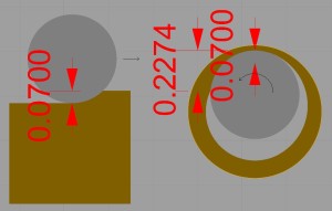
The problem I was having was that I could easily cut 0.8″ DOC, 0.07″ WOC linearly with my 0.5″ endmill no problem. It sounded good and cut just fine. Then I would drop the endmill down into a 0.5512″ drilled hole and interpolate out to a diameter of roughly 0.75″ using the exact same parameters and it had more chatter then an episode of The View. How could this be affecting the cut so drastically?
Well if we do a little analysis in CAD the magnitude of the problem immediately becomes apparent. The radial engagement drastically climbs when spiral milling a bore even though the step over is still only 0.07″. Interpolating using a 0.5″ endmill in a 0.5512″ bore effectively triples the radial engagement so that what we thought was a 0.07″ radial engagement producing 0.0039″ deflection is actually over 0.2″ of radial engagement producing 0.0086″ deflection. That’s over 40% engagement! No wonder it’s chattery. Move over Whoopi you’ve got some competition. Of course as the bore enlarges the radial engagement is not static, it changes and fortunately it declines as the endmill spirals out since the work is progressively not wrapped so tightly around the tool. So all one must do to calculate the appropriate step over for interpolation is to calculate what I call the magnum of arc. This is the maximum engagement that occurs at the end of the first fully engaged revolution of the cut just before the spiral arc takes the tool around to cutting previously relieved material. Then simply limit the step over to this, the maximum that the tool will ever radially engage in this spiral, as your desired radial engagement. What a mouthful.
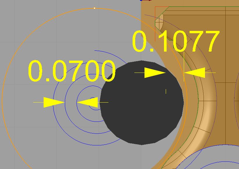
And that’s what I did. I reprogrammed the step over distance of the spiral to be something more commiserate to ensuring an actual radial load of 0.07″ or 14% of tool radius. This step over value actually ended up being only 0.0089 or almost 8 times less than what we thought and what had been previously programmed.
Both cuts have a 0.07″ step over but the circular interpolations results in radial engagement approaching 1/4″.
I started to write an equation that would define all of these parameters but decided that is probably better suited for someone who can actually plug it in to a nice mini-calc in an already existing program…ahem Bob. Perhaps input parameters for initial hole size if there is a pre-drilled hole or if plunge milling a hole size equal to the tool diameter (which would always bring back an initial 100% radial load because any radial motion away from a plunge will always initially be full engagement), and desired actual radial engagement. I envision the mini-calc simply grabbing the tool diameter from whatever active tool is and then once the adjusted step over is calculated saving it to the main cut width box. One can then simply input this new step over value into their CAM software when programming interpolation or spiral operations and not run the risk of grossly over engaging the tool. This feature would be especially useful in hard unforgiving materials.
While doing these cuts the deflection was also noted in the bore and the code was modified to leave approximately 0.004-0.005″ per side for the reamer.
On this cut I also lowered the rpm a little bit to eliminate some of the polar harmonics that was occurring. Now overall the cut sounds much better. Here is the endmill I’m using from Lakeshore Carbide:
Lakeshore Carbide extended length 1/2″ roughing endmill
I did finally notice a couple of tiny chips on the teeth of this endmill but it still runs great and could just be a cumulative effect from all the screeching cuts I’ve made with it this far. Time will tell with a new tool and better cuts.
Moving on, I couldn’t leave well enough alone. I decided to go ahead and try a full depth 0.4″ full slot cut on the bayonet lug with the 0.375″ rougher with the idea that I’m using more of the flutes which therefore will result in fewer overall cuts with the flute tips engaged (typically the first part to chip and ruin an otherwise good endmill). It turned out amazingly good. I’m always surprised at what this endmill does and it seems to like slotting better that anything else, it just gets dead quiet when doing its thing with full radial engagement.
I’ve made an order recently for more endmills and am going to try a similar 0.375″ rougher from Lakeshore Carbide they call the “fireplug”. It is a stub length, variable flute, variable helix, corner chamfer, thick core, Viagra coated, roughing endmill. So basically all the tricks of the trade to make the most rigid endmill possible. Ok maybe not Viagra coated but certainly prescription strength stiffness and with less vibrations than well never mind. I went with it because I analyzed all the cuts I do with this size endmill and determined that nothing is really in excess of 0.4 DOC. There is one cut that does exceed the flute length and that is the cleanup pass when gutting from the side but I can easily program around that. Anyway here is that endmill:
Lakeshore Carbide fireplug roughing endmill
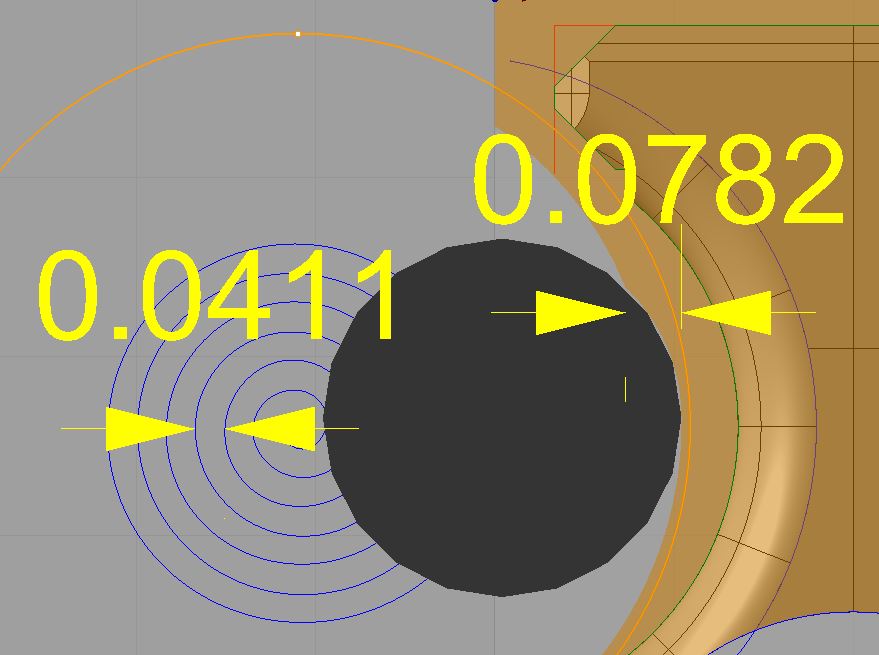
The spiral roughing for the profile suffers from the same phenomenon of radial overloading so had to use the same technique to tweak these cuts as well.
You can see the difference the 0.07″ step over and then adjusting it to a 0.0411″ step over has on the cut width albeit much less drastically due to the larger diameter circle. I have since modified the the current step over distance again but don’t feel like grabbing another screen shot but you get the idea.
So when experimenting with the profile pass again I took note of the part dimensions to asses the severity of deflection. My goal was leave 0.004″ per side for finishing but when I programmed it that way it actually left 0.007″ per side on top of that due to deflection. So I ran a spring pass reducing it to 0.002 on top of that. Then a second spring pass leaving 0.0005″ over that. Hmmm two spring passes is no good so I altered the code to only leave 0.002″ for finishing and one spring pass. This ended up leaving 0.00375″ per side for finishing…just about perfect.
Using the same finishing parameters as the previous videos but right to the surface dimension of the part this got to 0.00025″ over. Probably good enough but a spring pass got it dead nuts on target. This kind of accuracy is important because of the front roundover step. As shown in prior videos if the profile dimensions are slightly oversized (due to deflection) then the roundover tool will leave an unwanted ledge. Even so I still modified the round over tool path to take a wider berth leaving 0.005″ of stock and eliminating the finish pass to ensure reliability in production and withstand any minor variation. I also added back the finish passes on the chamfering ops.
There was also a strange problem when cutting the bayonet lug recesses. I zeroed everything just fine, made some cuts, then when I switched to the 0.1875″ endmill and resumed the program the machine moved maybe 0.1″ too far in the X direction and it plunged my endmill straight down into the part (which damaged the flute tips and destroyed the part). I paused it quickly and studied the situation. Finding nothing out of the ordinary except the position of my tool I didn’t do anything but re-run the program and it then went to the correct location and did the cut accurately. I then simply loaded another part, did all the cuts up to that point and it cut everything correctly. The only thing I can think of is an anomalous Mach 3 brain fart.
Bear with my boring narration in all my videos and perhaps especially this one. When I make these videos it is usually late at night (early in the morning) and I am almost invariably dead tired. However I have found that my videos and blog posts serve as almost like a public notebook or journal that I have found myself referring to all the time when programming.
Hmmm what did that cut with similar parameters sound like?
What kind of deflection did I get with that endmill and that DOC?
What RPM or feed seemed to chatter with that cut?
What feed gave me a better reamer finish?
Was coolant able to get in there and clear chips OK on that cut?
These are all questions that pop into my head while programming and while my actual notebook is quite useful nothing beats being able to actually go back and see and hear that cut again organized with the cut data right on the screen to go along with it. That’s why I continue to post redundant and what I can only imagine to be boring video to non-machine freaks and lately I have even been really recognizing the value of adding as much data and information as I possibly can to each installment. It helps me tremendously and I only hope you all find it interesting or helpful to you as well.
With the foresight of having a small backlog of footage I don’t need a crystal ball to tell you that the next installment will be 3D machining the main lightening pocket and breaking more tools. Yay.
Until next time, and hopefully not so far out.